
- Out-of-Stock
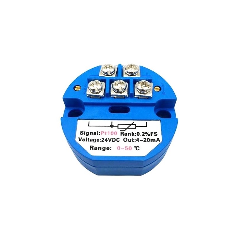


Specification:
Model : ATO-TEMPT-SBW
Accuracy : ≤0.2%FS
Power supply : DC 12-35V
Input signal : RTD (PT100, PT1000), thermocouple (E/K/S/B/T/J/N/R)
Output signal: 4-20mA
Transmission mode : 2-wire
Load resistance: 0~600Ω (DC 24V), rated load 250Ω
Temperature influence: ≤0.05/1℃
Mechanical vibration: f≤55Hz, amplitude<0.15mm
Working environment: Temperature: -25~+80℃, humidity: 5%~95%RH
Temperature transmitter supports optional PT100, PT1000, E/K/S/B/T/J/N/R type thermocouple input signal.
Tips: Temperature transmitter calibration
1.Calibrate the temperature transmitter on site, particularly the transmitter with thermocouple input. If there's automatic temperature compensation for reference end, the compensation lead method shall be adopted for connection calibration. When calibrating, the output impedance of the calibrator shall be smaller enough than the input impedance of the calibrated thermocouple temperature transmitter, otherwise a large measurement error may occur.
2. Adjustment before calibration. Use the method of changing input temperature signal to adjust the corresponding output lower limit value and output upper limit value, make it consistent with the lower and upper limits value of the standard. Do not adjust zero and range during the measurement process.
3. Calibration process. Selection of the calibration points is evenly distributed by measuring range. Generally no less than 5 points shall be selected, including the upper limit, the lower limit and the points near the 50% range. Read and record in turn from the lower limit to the upper limit and then reverse to the lower limit, measure for three cycles. Calculate the difference between the average value and the standard output value of the calibrated points within the 3 cycles through the comparison method, thus getting the error of all the calibrated points.
Measuring range chart:
Type of sensor Measuring range Minimum measuring range (difference value of upper and lower limits)
E 0~800℃ 300℃
K 0~1300℃ 400℃
S 0~1600℃ 600℃
B 0~1800℃ 800℃
T 0~400℃ 200℃
J 0~1200℃ 300℃
N 0~1200℃ 400℃
PT100 -200~+600℃ 50℃
PT1000 -200~+600℃ 50℃
Specification:
Model : ATO-TEMPT-SBW
Accuracy : ≤0.2%FS
Power supply : DC 12-35V
Input signal : RTD (PT100, PT1000), thermocouple (E/K/S/B/T/J/N/R)
Output signal: 4-20mA
Transmission mode : 2-wire
Load resistance: 0~600Ω (DC 24V), rated load 250Ω
Temperature influence: ≤0.05/1℃
Mechanical vibration: f≤55Hz, amplitude<0.15mm
Working environment: Temperature: -25~+80℃, humidity: 5%~95%RH